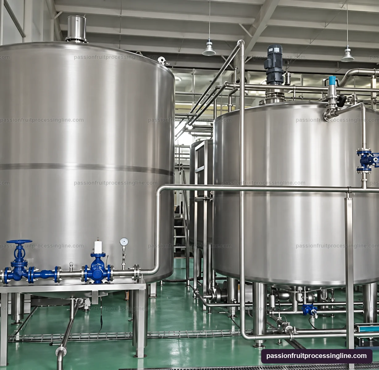
Bridge operating variation without making storage the process
Opening and finishing can deliver a varying liquid flow while a thermal unit or evaporator needs a controlled inlet. A buffer separates those short changes from the downstream process, provided its level range and feed controls have been designed for the actual duty.
Base the vessel on the liquid entering it, not the whole-fruit intake. Shells, rejected seeds, removed pulp and any formulation additions alter the mass balance before this point. Also distinguish gross vessel volume from the working volume available between the selected operating levels.
Match agitation to the required pulp distribution
Where product settling or separation would change the downstream specification, evaluate an agitation arrangement appropriate to the pulp content and viscosity. The objective is a consistent outlet stream without unnecessary vortexing, foam or seed damage.
A visible top drive identifies an agitated-vessel configuration, but the impeller, useful volume and mixing performance belong in the selected equipment specification. Heating or cooling provisions, if required, also need a stated purpose and utility duty.
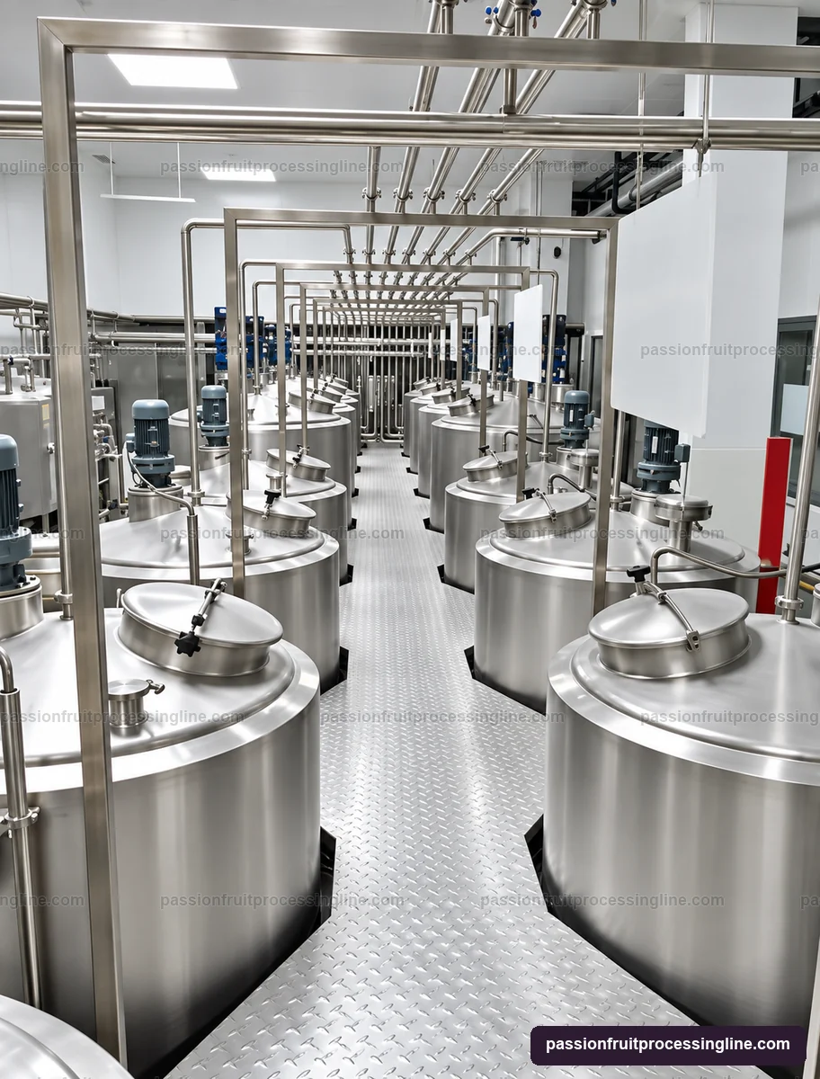
Specify the pump from the product and the receiving machine
| Duty input | Why it matters |
|---|---|
| Flow at the product temperature | Sets the transfer requirement at the actual viscosity |
| Seed, pulp and particle limits | Influences passage size and acceptable mechanical action |
| Pipe route and downstream pressure | Determines the required pressure duty and available suction conditions |
| Level and interlocks | Coordinates low-level protection and downstream readiness |
| Cleaning route | Defines drainability, valve positions and return connections |
Control product residence and provide complete drainage
For a known constant flow, nominal residence is usable volume divided by volumetric flow. Actual residence distribution changes with mixing, variable levels and start-stop operation. Set the permitted holding conditions through the product process plan rather than treating a large tank as an unrestricted waiting area.
Include the tank outlet, pump, bypasses and low points in the cleaning design. Show how the vessel is emptied between products and how the intended CIP flow reaches the connected equipment. Open collection surfaces may require a separate cleaning procedure.
In practice
Questions about this stage
How much buffer volume does the liquid section need?
Start with the actual incoming liquid flow, downstream demand, expected interruptions and permitted product holding conditions. Establish the usable volume between operating levels, then select the gross vessel volume and controls around that duty.